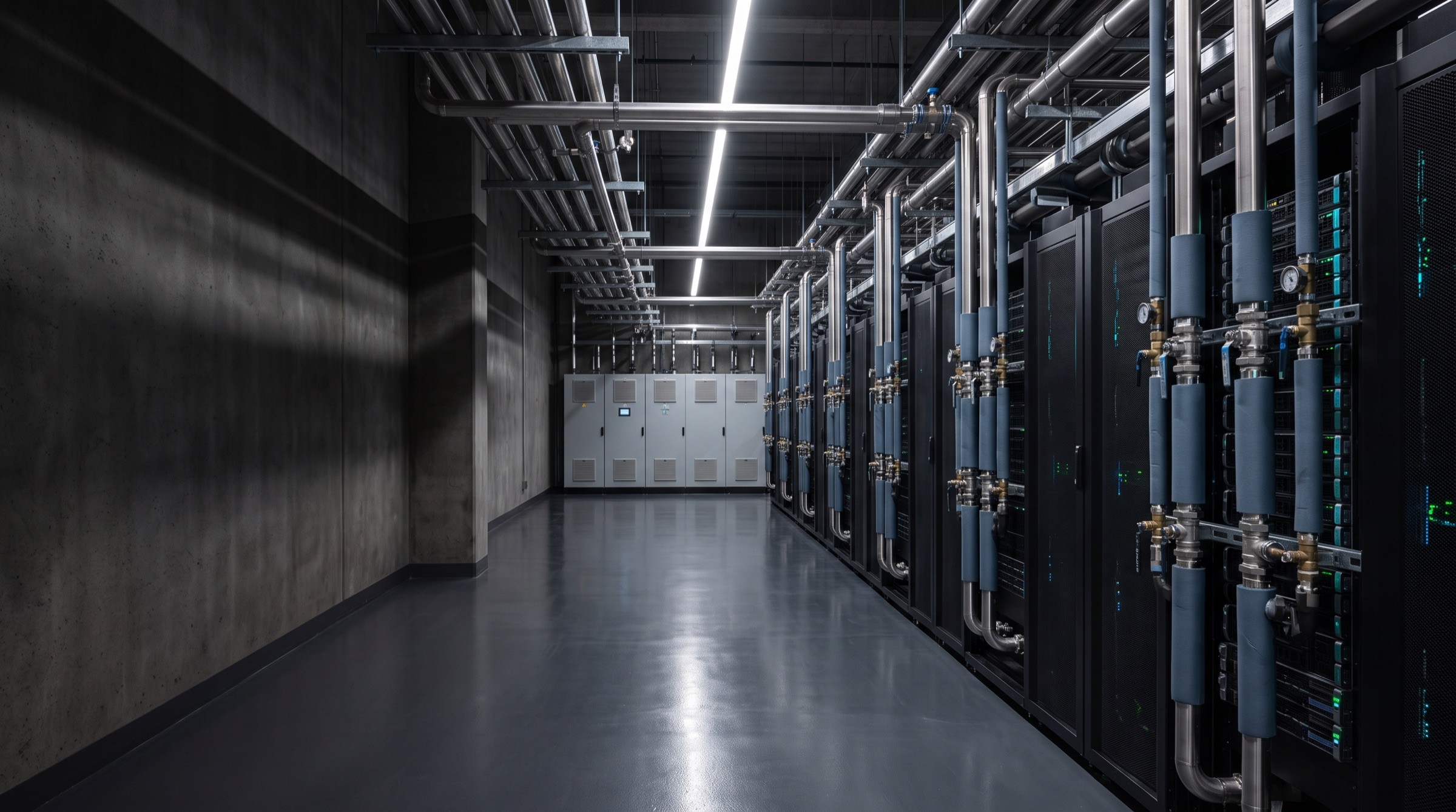

Liquid-cooled AI data center hall
LowHigh

Thermal view — illustrative visualisation, not measured data

AI infrastructure / Thermal engineering

Engineered to keep intelligence running.

Engineered to keep intelligence running.

Engineered to keep intelligence running.

Advanced liquid cooling and thermal infrastructure engineered for the demands of high-density AI computing.

Discuss Your Project
Explore Our Systems

The thermal challenge

More computing. More heat. Greater engineering demands.

More computing. More heat. Greater engineering demands.

More computing. More heat. Greater engineering demands.

Open AI server tray with direct-to-chip cold plates and braided coolant hoses

Fig. 01 — Direct-to-chip cold plates

Heat captured at the source

As computing density increases, thermal management becomes an increasingly important part of infrastructure design.

THERMGRID focuses on the cooling systems, engineered components and supporting infrastructure that help operators manage demanding thermal requirements — from the chip to the point where heat leaves the building.

Cooling approach vs. rack densityConceptual
Air cooling
Rear-door HX
Direct-to-chip
Immersion
Lower densityHigher density →

Indicative only. The right approach depends on the facility, the equipment and the system design.

Engineered systems

Cooling infrastructure, engineered as a system.

Cooling infrastructure, engineered as a system.

Cooling infrastructure, engineered as a system.

All systems
Liquid Cooling SystemsCoolant DistributionThermal ManagementHeat Rejection Infrastructure
01/ 04
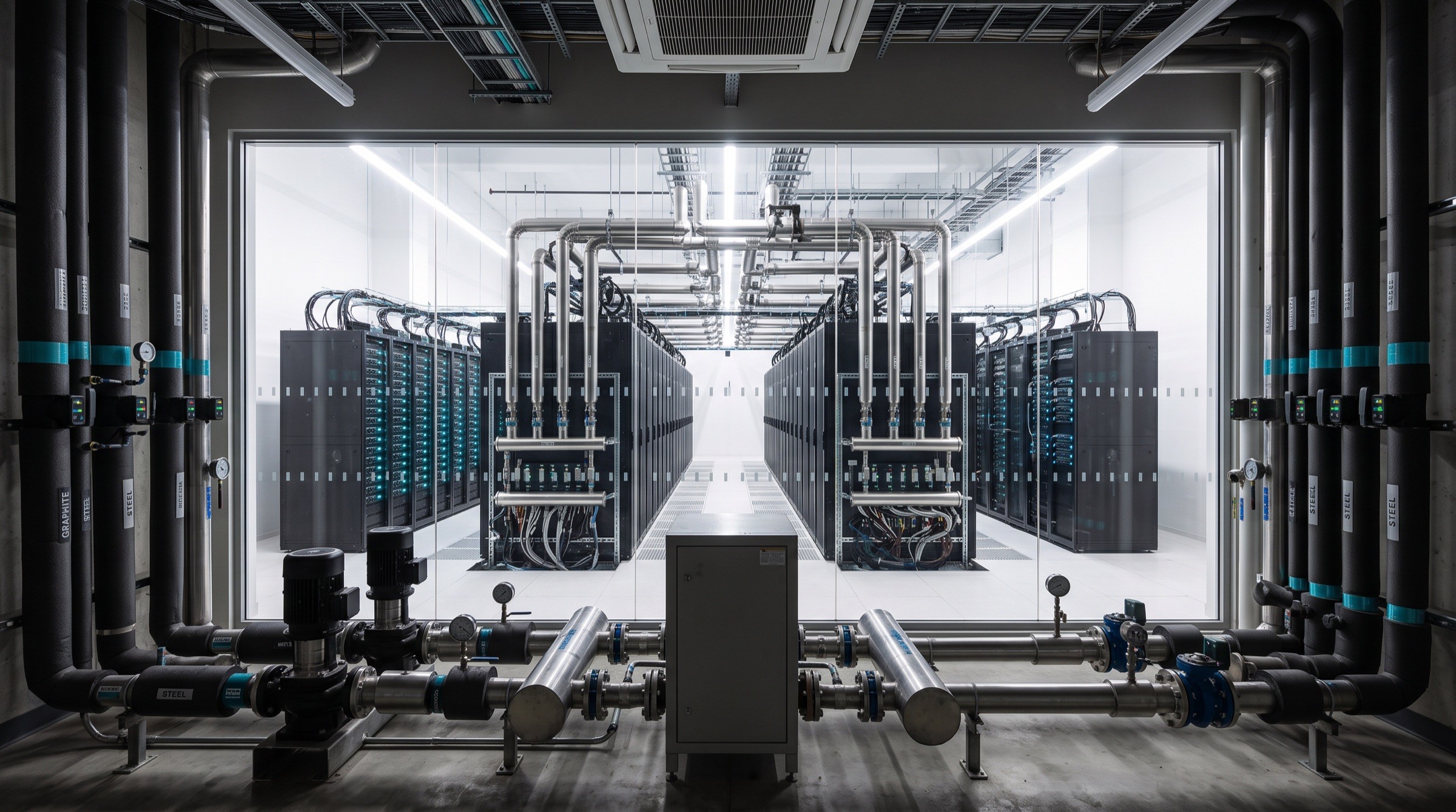
Fig. 02 — Rack manifold, quick-disconnect couplingsTHERMGRID systems

How the system works

From computing load to thermal control.

From computing load to thermal control.

From computing load to thermal control.

A simplified direct-to-chip architecture. Actual cooling architectures vary by facility, equipment and system design.

Fig. 06 — Liquid cooling loop, conceptual
Conceptual illustration · not to scale · not a design specificationView our systems
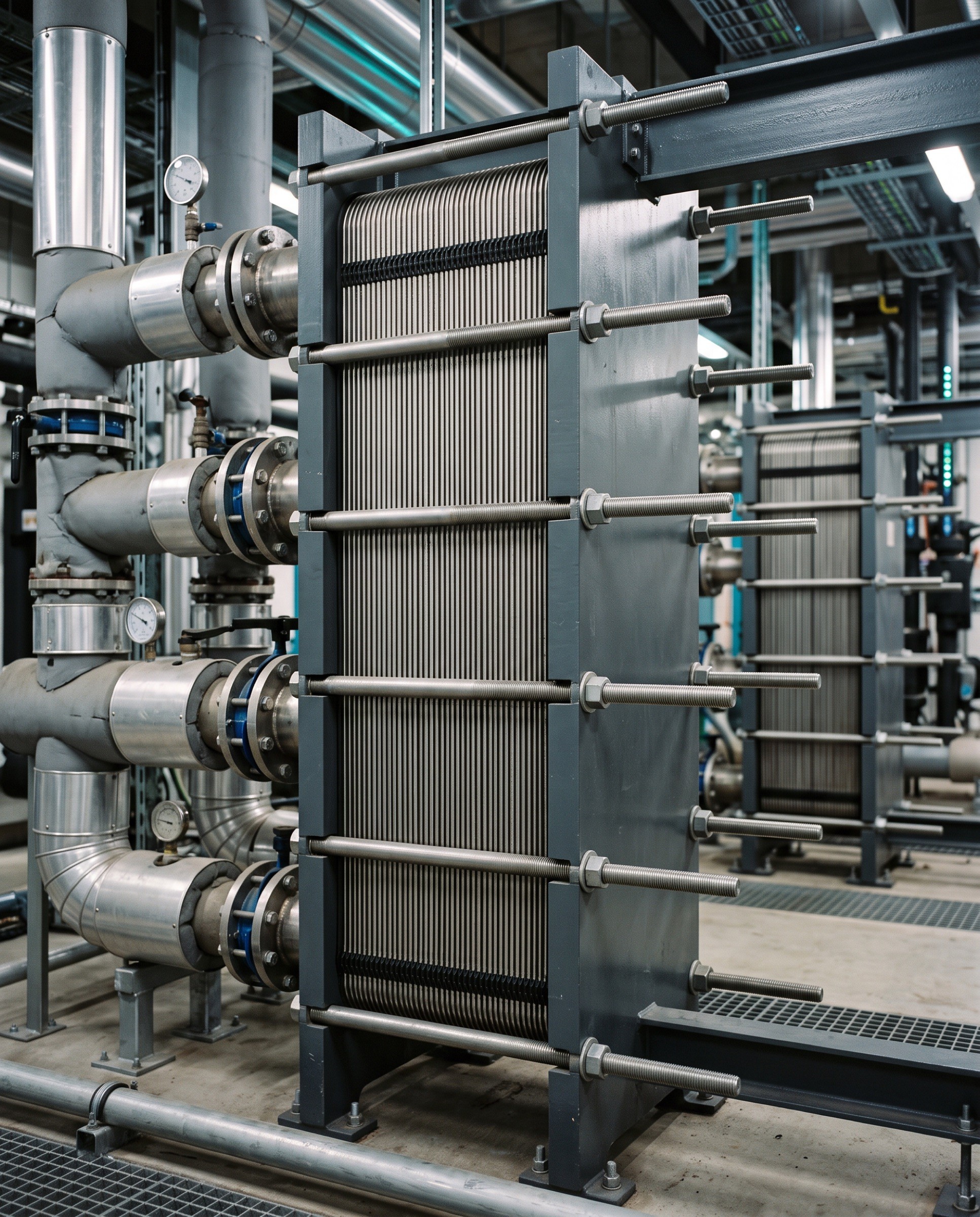
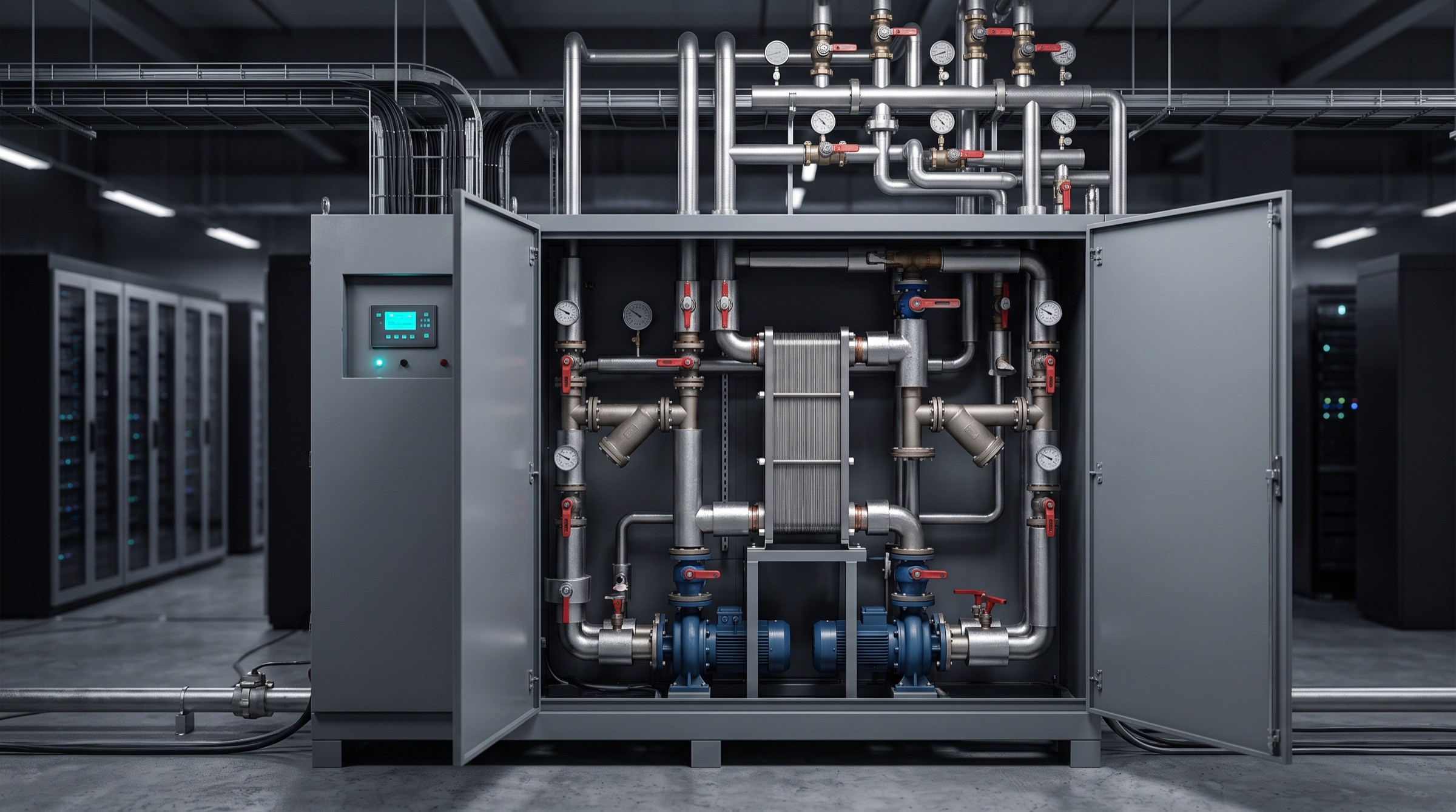
Coolant distribution unit with front doors open

Liquid cooling technology

Designed for the thermal demands of modern computing.

Designed for the thermal demands of modern computing.

Designed for the thermal demands of modern computing.

A coolant distribution unit sits between the racks and the building. How it is configured, connected and maintained shapes how the whole cooling system performs.

View Our Systems
How it works

Where THERMGRID fits

Infrastructure for demanding computing environments.

Infrastructure for demanding computing environments.

Infrastructure for demanding computing environments.

05 environments

AI & GPU infrastructure
A—0101 / 05

AI & GPU infrastructure

Context

Training and inference clusters concentrate large thermal loads into a small number of racks.

Engineering challenge

Moving heat away from the chip reliably as equipment generations change.

High-density facilities
A—02

High-density facilities

Context

Purpose-built halls where liquid cooling is planned into the building from the start.

Engineering challenge

Sizing the plant, pipework and distribution together, not as separate packages.

Hyperscale data centers
A—03

Hyperscale data centers

Context

Repeatable campus designs deployed in phases across multiple buildings.

Engineering challenge

Standardising cooling modules while adapting to each site's climate and constraints.

Colocation infrastructure
A—04

Colocation infrastructure

Context

Multi-tenant halls where some customers arrive with liquid-cooled equipment.

Engineering challenge

Adding liquid cooling capacity to live space without disrupting existing tenants.

Thermal engineering projects
A—05

Thermal engineering projects

Context

Retrofits, upgrades and studies where existing plant meets new thermal loads.

Engineering challenge

Understanding what the current system can support before anything is changed.

From requirement to system

Engineered around the application.

Engineered around the application.

Engineered around the application.

Stage 01

Understand

Understand

Establish operational requirements, computing density, thermal loads and facility constraints.

Stage 02

Design

Design

Develop an appropriate cooling architecture and define the system requirements.

Stage 03

Integrate

Integrate

Coordinate system components and integration requirements within the project scope.

Stage 04

Support

Support

Provide the relevant documentation, technical coordination and ongoing support where offered.

Featured project

High-Density Computing Cooling Infrastructure

High-Density Computing Cooling Infrastructure

High-Density Computing Cooling Infrastructure

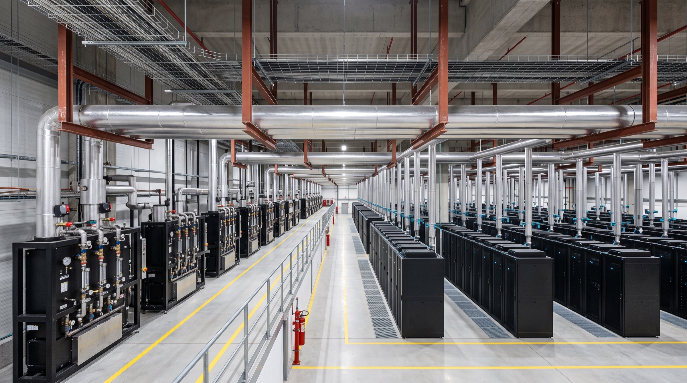
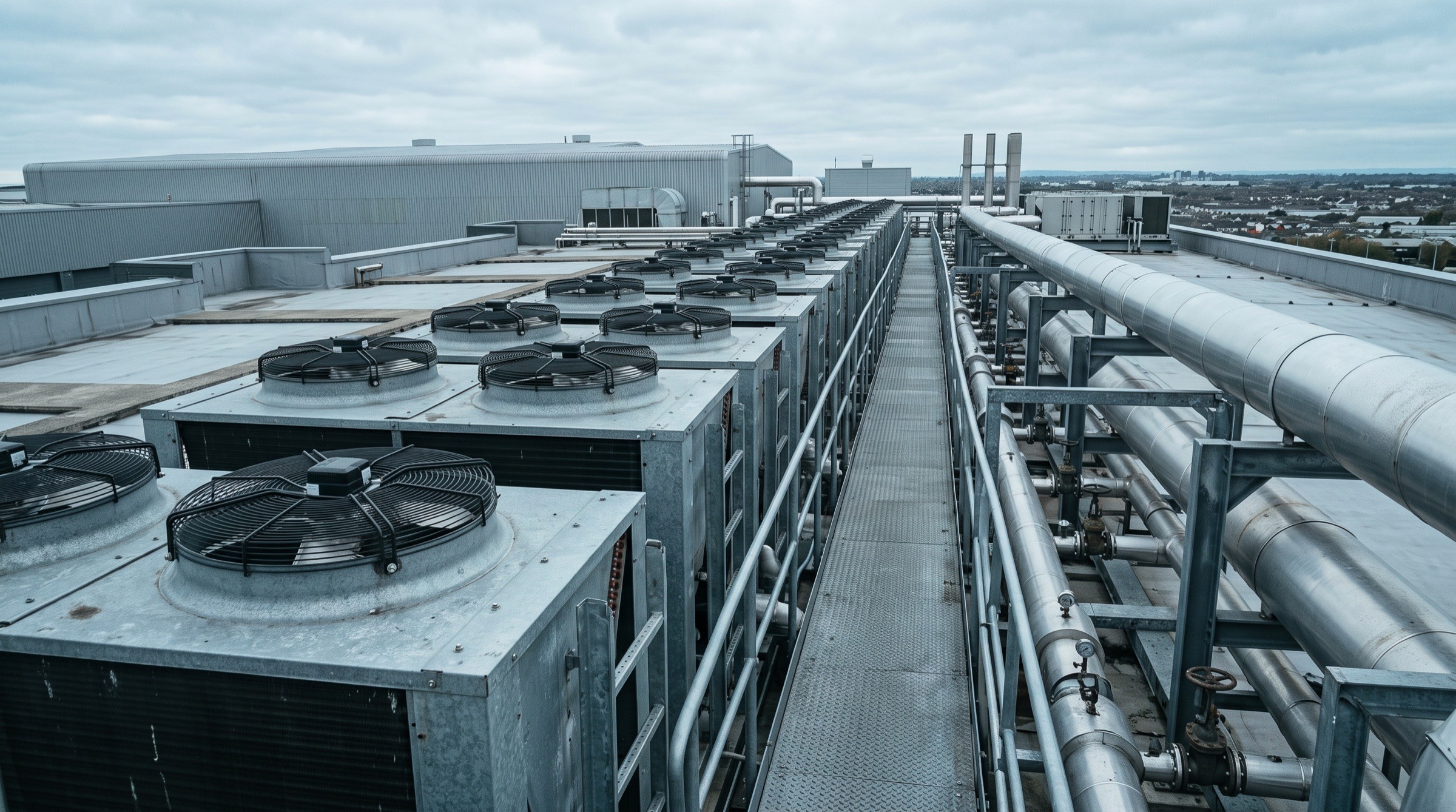
Wide view of a commissioned liquid cooling installation with overhead coolant headers and rack rows

Illustrative case study

An example of how a THERMGRID case study is presented: a new high-density hall planned around direct-to-chip liquid cooling from the outset.

Client

Demo client — not a real organisation

Facility type

High-density AI computing hall

Scope

Secondary loop, CDUs, heat rejection interface

Status

Illustrative template content

Read the case study

01 Context

Project context

A new hall intended for GPU clusters, with racks too dense for air cooling alone.

02 Challenge

Engineering challenge

Delivering liquid cooling to every row while keeping maintenance access clear.

03 Requirements

System requirements

Redundant distribution, separated loops and a phased build-out path.

04 Architecture

Proposed architecture

Row-level CDUs on a closed secondary loop, linked to facility water and dry coolers.

05 Installation

Installation considerations

Overhead headers coordinated with cable routes, with isolation points per row.

06 Outcome

Project outcome

A coordinated cooling system ready for phased commissioning. Values below are demo data.

Illustrative

12 rows

12 rows

served by the secondary loop

Illustrative

N+1

N+1

distribution redundancy

Illustrative

3 phases

3 phases

planned build-out

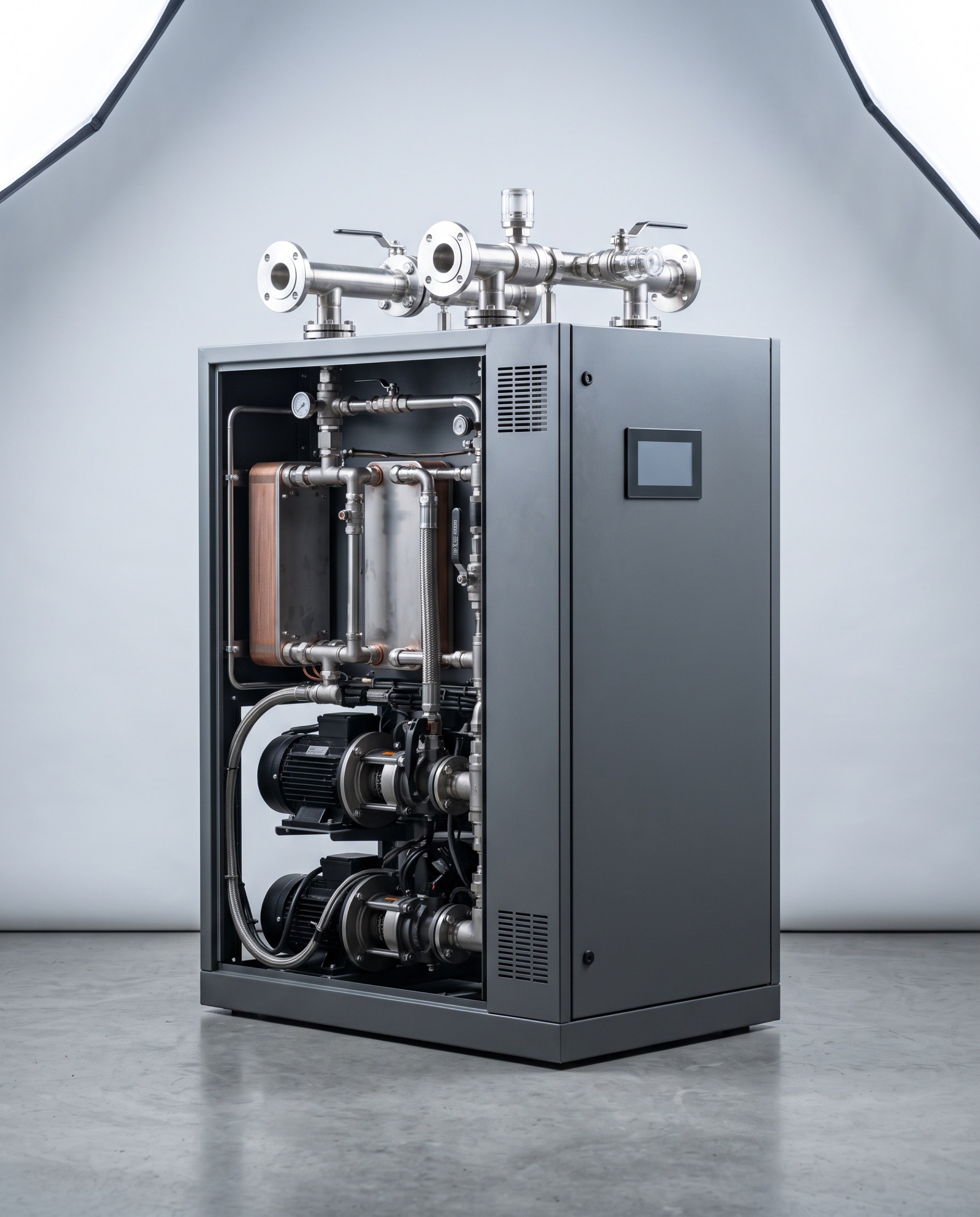
In-row coolant distribution unit photographed on a light grey studio background

Fig. 07 — In-row CDU, side panel removed

Product imagery

Technical capabilities

Specified for the project, not the brochure.

Specified for the project, not the brochure.

Specified for the project, not the brochure.

Every system is defined around the facility. This sheet shows how technical information is presented — the values are examples only.

Sheet TG-CDU-R

Example values

System category

Coolant distribution unit, in-row

Intended application

Direct-to-chip liquid cooling for high-density racks

Available configuration

Single or redundant pumps, front service access (example)

Integration considerations

Facility water interface, controls and monitoring, rack manifold connection

Documentation

General arrangement, schematics, O&M information (on request)

Project-specific requirements

Capacity, redundancy and connection details defined per project

Technical Enquiry
See the system diagram
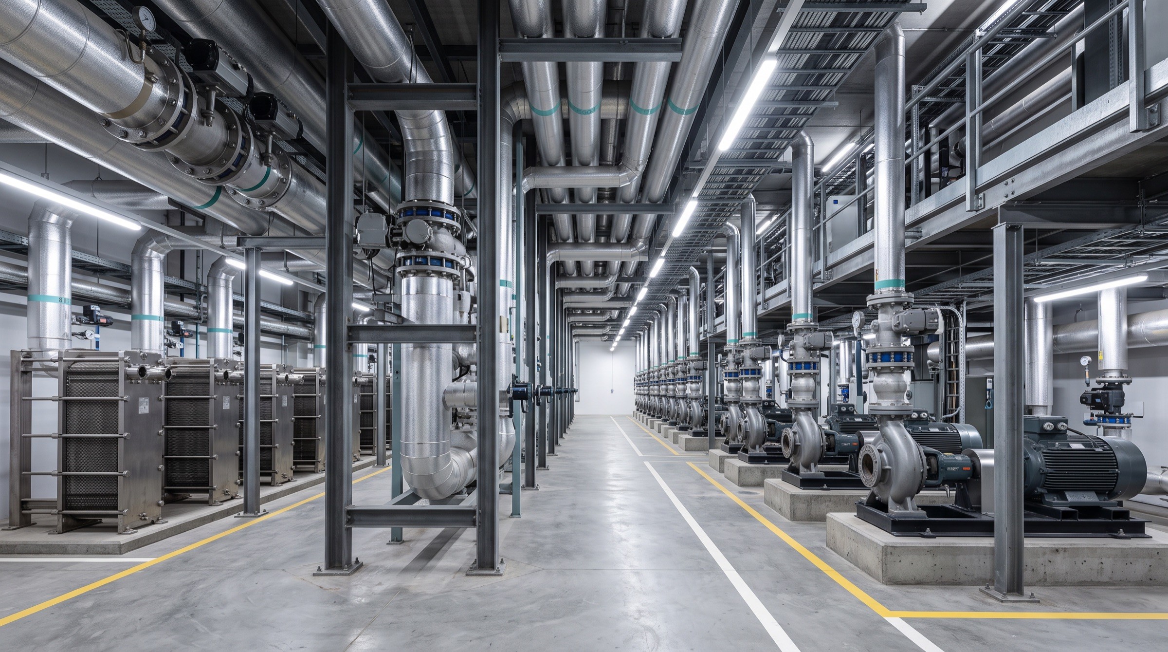
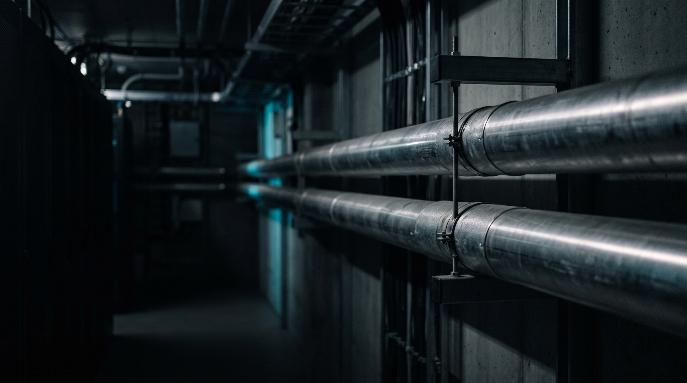
Insulated coolant pipework running along a data center ceiling

Why it matters

The infrastructure behind every workload.

The infrastructure behind every workload.

The infrastructure behind every workload.

Pressure gauge, temperature probe and transmitter on a stainless coolant line

Fig. 08 — Instrumentation on the secondary loop

01

Thermal design

The cooling architecture sets what the computing room can support over its life.

02

System integration

Racks, distribution and plant work as one system only when they are designed together.

03

Operational requirements

Redundancy, controls and monitoring follow how the facility will actually be run.

04

Maintainability

Access, isolation and documentation decide how safely a live system can be serviced.

About THERMGRID

Insights

Notes on thermal infrastructure.

Notes on thermal infrastructure.

Notes on thermal infrastructure.

All insights
Liquid-cooled AI data center hall

Start a conversation

Let's engineer your next cooling system.

Tell us about your facility, computing requirements and thermal infrastructure challenges.

Discuss Your Project
Technical enquiries

Facility

Location & type

Computing

Density & load

Stage

Concept → build

Response

Engineering team

Liquid-cooled AI data center hall

Start a conversation

Let's engineer your next cooling system.

Tell us about your facility, computing requirements and thermal infrastructure challenges.

Discuss Your Project
Technical enquiries

Facility

Location & type

Computing

Density & load

Stage

Concept → build

Response

Engineering team

Liquid-cooled AI data center hall

Start a conversation

Let's engineer your next cooling system.

Tell us about your facility, computing requirements and thermal infrastructure challenges.

Discuss Your Project
Technical enquiries

Facility

Location & type

Computing

Density & load

Stage

Concept → build

Response

Engineering team

Data center cooling & thermal infrastructure. Demonstration brand — company details, projects and values are illustrative.

Discuss Your Project

© 2026 THERMGRID. Demonstration template — all content illustrative.

Data center cooling & thermal infrastructure. Demonstration brand — company details, projects and values are illustrative.

Discuss Your Project

© 2026 THERMGRID. Demonstration template — all content illustrative.

Data center cooling & thermal infrastructure. Demonstration brand — company details, projects and values are illustrative.

Discuss Your Project

© 2026 THERMGRID. Demonstration template — all content illustrative.

Create a free website with Framer, the website builder loved by startups, designers and agencies.