/

/

Coolant distribution

System

02

Coolant Distribution

Coolant Distribution

Coolant Distribution

The coolant distribution unit sits between the racks and the building — pumping, filtering and controlling the secondary loop.

Category

Engineered system

Scope

Design · integration · commissioning

Content

Illustrative demo

Pumps, valves and pipework inside a coolant distribution unit

Overview

Engineered distribution systems, manifolds and supporting components that deliver coolant where it is needed, at the conditions the equipment requires.

Engineered distribution systems, manifolds and supporting components that deliver coolant where it is needed, at the conditions the equipment requires.

Engineered distribution systems, manifolds and supporting components that deliver coolant where it is needed, at the conditions the equipment requires.

A CDU separates the technology cooling loop from the facility water system through a heat exchanger. It keeps the coolant serving the IT equipment clean, at the right conditions and under control.

THERMGRID specifies and integrates in-row and centralised distribution, with redundancy and controls set by the operating strategy of each site.

System components

What the system is made of.

What the system is made of.

What the system is made of.

Pumps

Circulate coolant through the secondary loop, typically with redundancy.

Heat exchanger

Transfers heat from the secondary loop to facility water while keeping the fluids separate.

Filtration

Maintains coolant quality for cold plates with fine internal channels.

Controls & monitoring

Regulate flow and conditions, and report to the building management system.

Isolation valves

Allow components to be serviced while the loop remains in operation.

Where it sits

Its place in the thermal path.

Its place in the thermal path.

Its place in the thermal path.

Fig. 06 — Liquid cooling loop, conceptual
Conceptual illustration · not to scale · not a design specificationView our systems

Engineering considerations

Decisions that shape the system.

Decisions that shape the system.

Decisions that shape the system.

Redundancy

Pump and unit redundancy follow the availability target of the facility.

Placement

In-row or centralised units are chosen around space, pipework and maintenance access.

Controls strategy

Set points, alarms and failover behaviour are defined before commissioning.

Capacity growth

Units and headers allow for additional racks in later phases.

Integration requirements

  • Facility water temperatures and pressures

  • Electrical supply and redundancy

  • BMS / DCIM integration

  • Floor loading and access routes

  • Fill, drain and water treatment

Every integration item is agreed with the project team before design is frozen — so interfaces are defined, not discovered on site.

Technical Enquiry
Front of a coolant distribution unit with its control panel

Fig. 01 — System detail

Product view of a coolant distribution unit

Fig. 02 — In context

All systems

Explore the full thermal path.

Explore the full thermal path.

Explore the full thermal path.

→

→

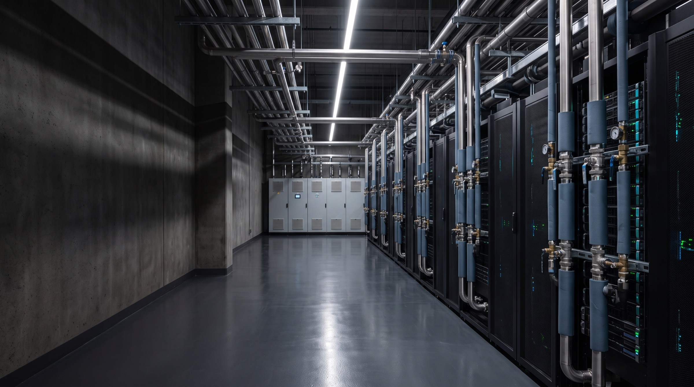
Liquid-cooled AI data center hall

Start a conversation

Let's engineer your next cooling system.

Tell us about your facility, computing requirements and thermal infrastructure challenges.

Discuss Your Project
Technical enquiries

Facility

Location & type

Computing

Density & load

Stage

Concept → build

Response

Engineering team

Liquid-cooled AI data center hall

Start a conversation

Let's engineer your next cooling system.

Tell us about your facility, computing requirements and thermal infrastructure challenges.

Discuss Your Project
Technical enquiries

Facility

Location & type

Computing

Density & load

Stage

Concept → build

Response

Engineering team

Liquid-cooled AI data center hall

Start a conversation

Let's engineer your next cooling system.

Tell us about your facility, computing requirements and thermal infrastructure challenges.

Discuss Your Project
Technical enquiries

Facility

Location & type

Computing

Density & load

Stage

Concept → build

Response

Engineering team

Data center cooling & thermal infrastructure. Demonstration brand — company details, projects and values are illustrative.

Discuss Your Project

© 2026 THERMGRID. Demonstration template — all content illustrative.

Data center cooling & thermal infrastructure. Demonstration brand — company details, projects and values are illustrative.

Discuss Your Project

© 2026 THERMGRID. Demonstration template — all content illustrative.

Data center cooling & thermal infrastructure. Demonstration brand — company details, projects and values are illustrative.

Discuss Your Project

© 2026 THERMGRID. Demonstration template — all content illustrative.

Create a free website with Framer, the website builder loved by startups, designers and agencies.