System
04
Every watt captured at the chip has to leave the building. Heat rejection is where the cooling system meets the climate.
Category
Engineered system
Scope
Design · integration · commissioning
Content
Illustrative demo

Overview
Facility water carries heat from the CDUs to plant on the roof or in the yard, where it is rejected to the atmosphere — or, where feasible, made available for reuse.
THERMGRID designs and integrates the facility water system, heat exchangers and heat rejection plant around the site climate and the loads they serve.
System components
Dry coolers
Fan-assisted coils that reject heat to ambient air.
Adiabatic assistance
Optional pre-cooling of air on warmer days, where water use allows.
Plate heat exchangers
Separate loops and allow interfaces with other systems.
Facility water pipework
Headers and risers between plant and white space.
Pumping stations
Circulate facility water with appropriate redundancy.
Where it sits
Engineering considerations
Site climate
Ambient conditions drive plant sizing and the operating envelope.
Water use
Dry, adiabatic and other approaches are compared against local constraints.
Acoustics & space
Roof and yard space, noise limits and maintenance access shape the layout.
Heat reuse
Interfaces for heat recovery can be allowed for where there is a demand.
Integration requirements
Roof or yard structure
Planning and acoustic limits
Water availability
Electrical capacity for fans and pumps
Heat reuse opportunities
Every integration item is agreed with the project team before design is frozen — so interfaces are defined, not discovered on site.
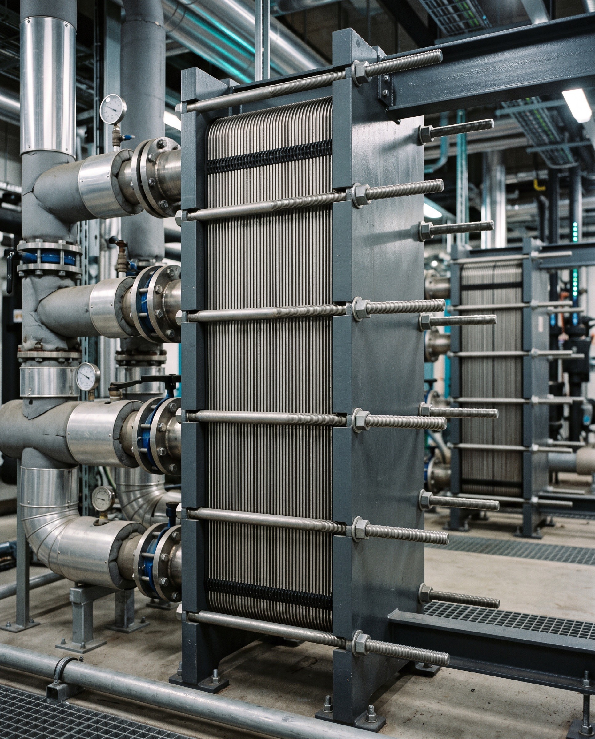
Fig. 01 — System detail

Fig. 02 — In context
All systems