/

/

Nordic campus

Illustrative case study

Nordic Campus Heat Rejection

Nordic Campus Heat Rejection

Nordic Campus Heat Rejection

Facility water and dry cooler infrastructure for a cold-climate campus.

Type

Heat rejection

Region

Nordics — illustrative

Year

Demo

Client

Demo — not a real organisation

Data center campus in a cold Nordic landscape

Context

A two-building campus in a cold climate, where ambient conditions favour dry heat rejection for much of the year.

A two-building campus in a cold climate, where ambient conditions favour dry heat rejection for much of the year.

A two-building campus in a cold climate, where ambient conditions favour dry heat rejection for much of the year.

Requirements

  • Dry heat rejection sized for the site climate

  • Freeze protection strategy

  • Interfaces for potential heat reuse

  • Low maintenance access at roof level

Engineering challenge

Designing plant that performs across a wide temperature range, including protection against freezing during low-load periods.

Proposed system

Rooftop dry coolers on a glycol facility loop, separated from the building water by plate heat exchangers, with a valved interface for future heat recovery.

Rooftop dry coolers on a glycol facility loop, separated from the building water by plate heat exchangers, with a valved interface for future heat recovery.

Rooftop dry coolers on a glycol facility loop, separated from the building water by plate heat exchangers, with a valved interface for future heat recovery.

Integration approach

Plant layout was coordinated with roof structure, snow loading and access walkways, with pipework routed through dedicated risers.

Outcome

What the project delivered.

What the project delivered.

What the project delivered.

Illustrative values

Illustrative

2

2

2

buildings

on a shared facility loop

Illustrative

1

1

1

interface

reserved for heat reuse

Illustrative

Dry

Dry

Dry

heat rejection approach

Rooftop dry coolers rejecting heat from a data center

Fig. 01 — On site

Valve on insulated coolant pipework

Fig. 02 — System detail

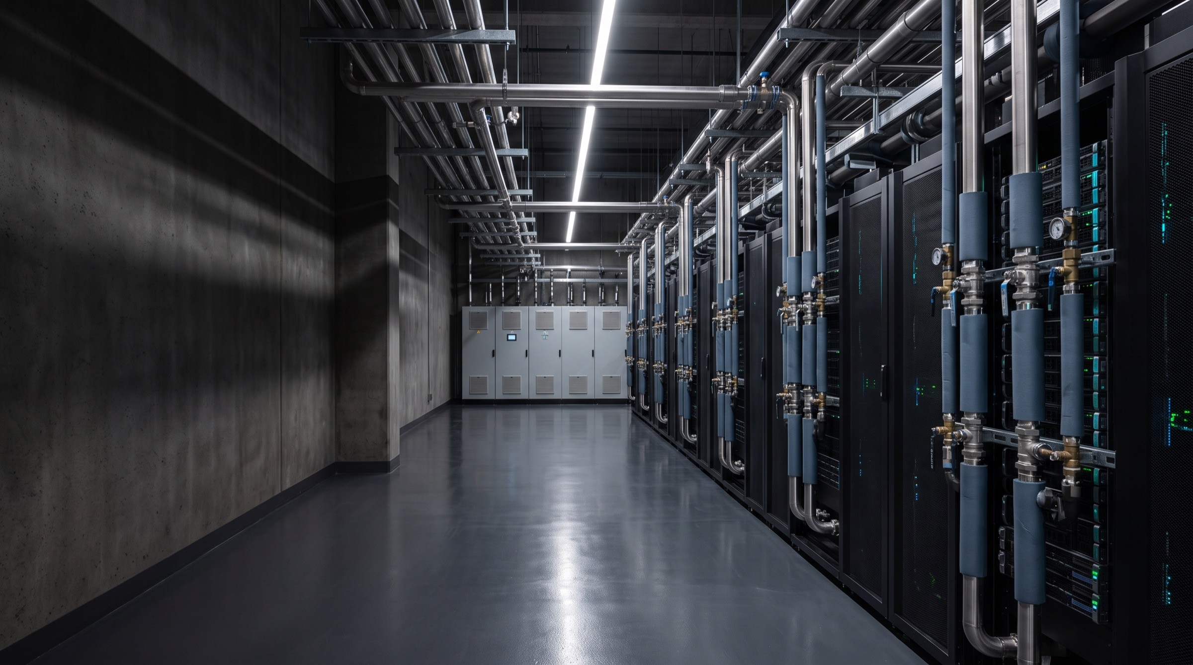
Liquid-cooled AI data center hall

Start a conversation

Let's engineer your next cooling system.

Tell us about your facility, computing requirements and thermal infrastructure challenges.

Discuss Your Project
Technical enquiries

Facility

Location & type

Computing

Density & load

Stage

Concept → build

Response

Engineering team

Liquid-cooled AI data center hall

Start a conversation

Let's engineer your next cooling system.

Tell us about your facility, computing requirements and thermal infrastructure challenges.

Discuss Your Project
Technical enquiries

Facility

Location & type

Computing

Density & load

Stage

Concept → build

Response

Engineering team

Liquid-cooled AI data center hall

Start a conversation

Let's engineer your next cooling system.

Tell us about your facility, computing requirements and thermal infrastructure challenges.

Discuss Your Project
Technical enquiries

Facility

Location & type

Computing

Density & load

Stage

Concept → build

Response

Engineering team

Data center cooling & thermal infrastructure. Demonstration brand — company details, projects and values are illustrative.

Discuss Your Project

© 2026 THERMGRID. Demonstration template — all content illustrative.

Data center cooling & thermal infrastructure. Demonstration brand — company details, projects and values are illustrative.

Discuss Your Project

© 2026 THERMGRID. Demonstration template — all content illustrative.

Data center cooling & thermal infrastructure. Demonstration brand — company details, projects and values are illustrative.

Discuss Your Project

© 2026 THERMGRID. Demonstration template — all content illustrative.

Create a free website with Framer, the website builder loved by startups, designers and agencies.