/

/

Colocation retrofit

Illustrative case study

Colocation Liquid Cooling Retrofit

Colocation Liquid Cooling Retrofit

Colocation Liquid Cooling Retrofit

Adding liquid cooling to a live multi-tenant hall.

Type

Retrofit

Region

Western Europe — illustrative

Year

Demo

Client

Demo — not a real organisation

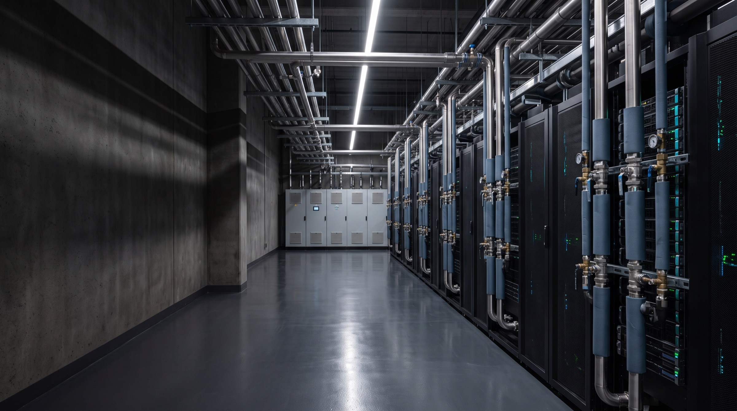
New overhead pipework installed above a live colocation hall

Context

An operating colocation hall where a new customer required liquid cooling for part of the space, while existing tenants remained air cooled.

An operating colocation hall where a new customer required liquid cooling for part of the space, while existing tenants remained air cooled.

An operating colocation hall where a new customer required liquid cooling for part of the space, while existing tenants remained air cooled.

Requirements

  • No disruption to live tenants

  • A dedicated liquid-cooled zone

  • Clear demarcation of responsibilities

  • Capacity for further zones later

Engineering challenge

Installing new overhead pipework and distribution above live equipment, within the existing plant capacity.

Proposed system

A modular in-row CDU zone connected to an extended facility water loop, with overhead secondary pipework installed in protected work areas.

A modular in-row CDU zone connected to an extended facility water loop, with overhead secondary pipework installed in protected work areas.

A modular in-row CDU zone connected to an extended facility water loop, with overhead secondary pipework installed in protected work areas.

Integration approach

Works were sequenced around tenant windows, with temporary protection, method statements and staged pressure testing.

Outcome

What the project delivered.

What the project delivered.

What the project delivered.

Illustrative values

Illustrative

1

1

1

zone

converted in the first phase

Illustrative

0

0

0

planned tenant outages

Illustrative

2

2

2

zones

allowed for in future

Data hall seen through a glass partition

Fig. 01 — On site

Coolant distribution unit installed beside a row of server racks

Fig. 02 — System detail

Liquid-cooled AI data center hall

Start a conversation

Let's engineer your next cooling system.

Tell us about your facility, computing requirements and thermal infrastructure challenges.

Discuss Your Project
Technical enquiries

Facility

Location & type

Computing

Density & load

Stage

Concept → build

Response

Engineering team

Liquid-cooled AI data center hall

Start a conversation

Let's engineer your next cooling system.

Tell us about your facility, computing requirements and thermal infrastructure challenges.

Discuss Your Project
Technical enquiries

Facility

Location & type

Computing

Density & load

Stage

Concept → build

Response

Engineering team

Liquid-cooled AI data center hall

Start a conversation

Let's engineer your next cooling system.

Tell us about your facility, computing requirements and thermal infrastructure challenges.

Discuss Your Project
Technical enquiries

Facility

Location & type

Computing

Density & load

Stage

Concept → build

Response

Engineering team

Data center cooling & thermal infrastructure. Demonstration brand — company details, projects and values are illustrative.

Discuss Your Project

© 2026 THERMGRID. Demonstration template — all content illustrative.

Data center cooling & thermal infrastructure. Demonstration brand — company details, projects and values are illustrative.

Discuss Your Project

© 2026 THERMGRID. Demonstration template — all content illustrative.

Data center cooling & thermal infrastructure. Demonstration brand — company details, projects and values are illustrative.

Discuss Your Project

© 2026 THERMGRID. Demonstration template — all content illustrative.

Create a free website with Framer, the website builder loved by startups, designers and agencies.